BACKGROUND
Most older Fluke Scopemeter portable oscilloscopes utilized NiCd or NiMH battery packs, which are by today's standards, subpar. Self-discharge was my biggest pet peeve - sometimes it would sit for a few weeks until I needed it, and more often than not the battery was dead!
This project aimed to not only replace the battery pack but also to simulate the original charge levels of the 4xNiCD, therefore retaining the original battery "fuel meter" and allowing safe early-warning shutdown when the batteries were depleted.
In addition this circuit had to safely remain installed if and when the AC adaptor was connected. No provisions were given for charging, simply because it is easy enough to remove and charge externally. For me anyway.
Lastly the circuit needed some form of low battery protection, to prevent over discharge of the Li-ion cells.
NOTE: prints below are for reference only! Feel free to email me for the most up to date versions.
UPDATES
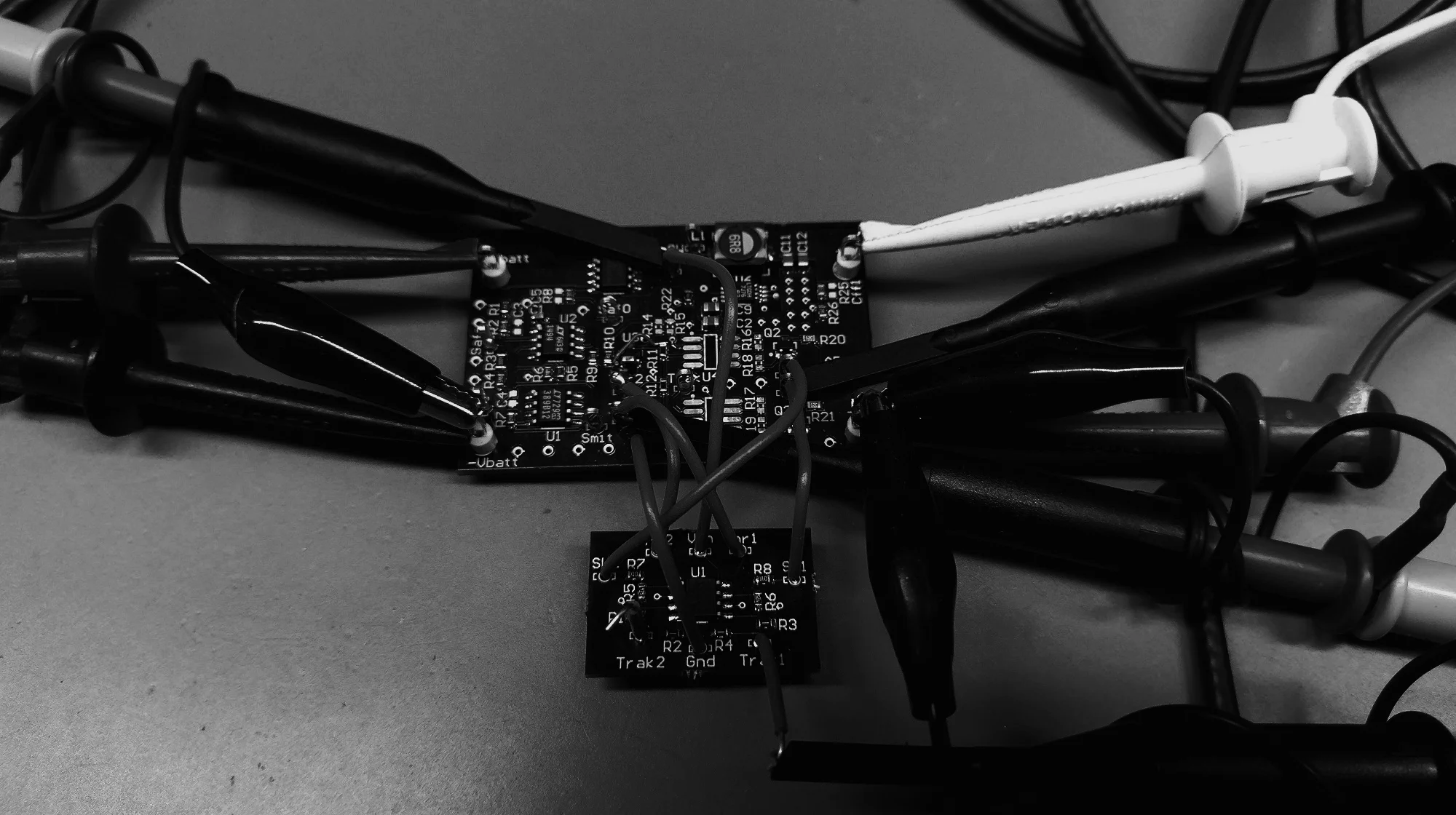
PCB has been ordered, populated, and testing is ongoing!

I've since changed the LM311 to a push-pull out TLC3702CD, which features a much lower quiescent current. I've also added hysteresis to the comparator in order to combat some minor oscillations at switching. Lastly the series gate resistor values are updated to reflect the actual value used (in order to limit output current to 15mA due to gate capacitance).
Updated circuit here:

ORIGINAL DESIGN:
Safety:
An under-voltage lockout circuit was first designed (based on reference design) with hysteresis. Cutoff voltage was set to 6.0V (2x18650 cells). Hysteresis is set to approximately 200mV: battery voltage must rise to above 6.2V in order to reset the cutout.

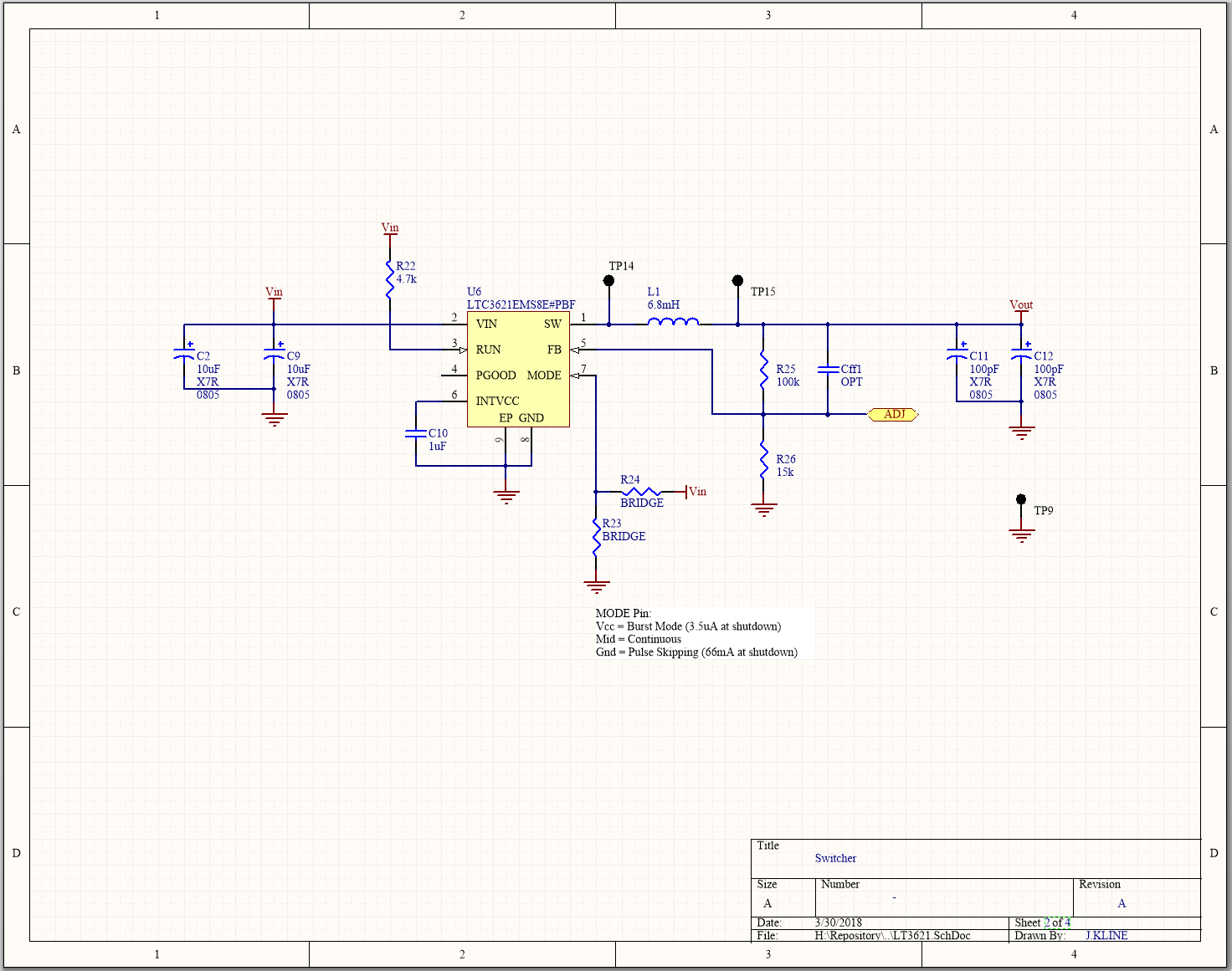
Switcher:
The heart of the circuit is the switching regulator. The switcher regulates based on a programmed feedback: three output levels are obtained, 4.5V (low battery indication), 6.5V, and 7.9V.
At this point the battery is isolated from the electronics of the Fluke - any applied voltage to the output of this regulator effectively shuts it down, and will not pass current back into the battery.
Tracker:
This circuit sets the programmable output based on the battery input voltage. As the battery drains, differing output voltage are programmed to both maximize efficiency and provide battery fuel gauge feedback to the user.
(ignore the duplicate R1/R2 designators - this was an early document)
Keen observers will note that this is not the typical arrangement for hysteresis, with the positive feedback being applied to the *sensed* pin. This was done for simplicity so that no "logic" inversion was necessary at the output.

